Journal Club 149

Radiation tolerance analysis of 4H-SiC PIN diode detectors for neutron irradiation

Silicon carbide (SiC) detector shows sufficient merits for the pplication of radiation measurement in harsh neutron radiation fields due to the strong radiation tolerance, good environment adaptability, and excellent electrical properties. In order to meet the demand for higher precision measurements, the eliability of SiC detectors under harsh neutron irradiation nvironments must be characterized. In this work, electrical characteristics, α-particle response, and pulse response speed of 4H-SiC PIN diode detectors were carefully investigated under MeV equivalent neutron irradiation fluence from \(5 × 10^{12} cm^{−2}\) to \(1 × 10^{1} cm^{−2}\) . Before neutron irradiation, SiC detector showed dark current as low as 10 pA at 200 V bias, with superior charge collection efficiency of more than 98%, perfect energy resolution within 0.9%, and ltrafast response speed with a rise time and decay time of 2.1 s and 5.9 ns, respectively. After a neutron irradiation at luence of 1 × 1014 cm−2, noticeable changes were found in the forward IV characteristics of SiC detector, but the dark current was stable below 1 nA, with only 5.7% and 0.26% degradation in charge collection efficiency and energy resolution respectively, and the pulse response speed remained unchanged. These results demonstrate 4H-SiC PIN diode detector has superior neutron radiation tolerance, and the obtained evolution characteristics are very valuable for improving the measuring accuracy of SiC detectors in the intense neutron field.

Further reading: R.L. Gao et al., “Effect of Very High-Fluence Proton Radiation on 6H-SiC Photoconductive Proton Detectors,” in Sensors and Actuators A: Physical,Volume 333,2022, doi: 10.1109/LED.2019.2949174.

Journal Club 148

Effect of Very High-Fluence Proton Radiation on 6H-SiC Photoconductive Proton Detectors

In this work, the effect of very high-fluence 100 MeV proton radiation on the performance of 6H-SiC photoconductive proton detectors is studied. The irradia- tion fluence is up to \(1.6\times10^{17}cm^{−2}\) and the degradation process of the SiC detector is continuously monitored for the first time. Before proton irradiation, the detector shows a low dark current of ∼ \(0.8 nA/cm^{2}\) at 1000 V bias. As the irradiation fluence increases, the dark current continuously drops, which should be caused by irradiation damage induced carrier compensation defects. Meanwhile, the output current of the SiC detector shows an exponential decay behavior and tends to saturate at irradiation fluence up to \(5\times10^{16}cm^{−2}\). At the end of the very high fluence irradiation test, the detector still exhibits ∼20% of its original output current value, suggesting the excellent radiation hardness of SiC for proton detection.

Further reading: Q. Liu et al., “Effect of Very High-Fluence Proton Radiation on 6H-SiC Photoconductive Proton Detectors,” in IEEE Electron Device Letters, vol. 40, no. 12, pp. 1929-1932, Dec. 2019, doi: 10.1109/LED.2019.2949174.

Journal Club 147

Correlation between structural defects and carrier lifetime

In 4H SiC substrate and epitaxial films, due to the influence of epitaxial process and growth conditions, there are many structural defects in the SiC epitaxial layer, such as thread dislocation TSD, thread edge dislocation TEDS, base plane dislocation BPDS, microtubule super TSD, 10 °low angle grain boundary, endogenous stacking faults, carrot shaped morphological defects, etc. These defects will affect the performance of the device more or less.

Of course, the characterization means of many defects are gradually improved. In order to eliminate the influence of defects, it is necessary to understand these means. First and foremost, time resolved photoluminescence (TRPL) is a very effective means to measure the radiative recombination between excitons and donors, and cathodoluminescence is also a good means to characterize the lifetime.

By providing electron beams to samples, the lifetime distribution can be well obtained. Other methods can provide a good relationship between the needle sample and the life. In addition, the comparison between the defects and the life diagram can well show that these structural defects do have a certain impact on the effective life of local carriers.

Further reading: J. Bergman,O. Kordina,E. Janzén,“Time Resolved Spectroscopy of Defects in SiC”,in,phys.stat.sol.(a)162,65(1997) Serguei I.Maximenko,Jaime A. Freitas Jr.,Paul B. Klein,Amitesh Shrivastava,and TangaliS. Sudarshan, “Cathodoluminescence study of the properties of stacking faults in 4H-SiC homoepitaxial layers”,in,Appl.Phys.Lett.94,092101(2009) J.Hassana and J.P.Bergman,“Influence of structural defects on carrier lifetime in 4H-SiC epitaxial layers:Optical lifetime mapping”,in,Journal of Applied Physics 105,123518(2009) Nadeemullah A. Mahadik, Robert E.Stahlbush, Joshua D. Caldwell,Michael O’Loughlin, and Albert Burk, “Correlation of Extended Defects on Carrier Lifetime in Thick SiC Epilayers”,in,Materials Science Forum Vols.717-720(2012)pp297-300

Journal Club 146

Growth habits of SiC on two different types of substrates

First,growth on nonplanar substrates。The experimental conditions are as follows: 1.Growth method: gas phase crystalline method

2.Countertop groove: a method of etching by reactive ions. 1-10um wide, 2um deep

3.Original materials: SiH4 and C3H8 provide silicon and carbon sources, triethylaluminum for p-shaped doping ,Heterogeneous, N2 for n-shaped doping,

4.Growth conditions: 1620 degrees Celsius, reaction internal pressure 800 mbar This paper studies the difference between the two crystal orientations and the growth layer under the two C/Si。The conclusion is as follows:

1.Parallel to the [1 ̄100] direction, for different C/Si, (C/Si=1.2 and C/Si=4), the top of the step can be fitted and grow slowly, when the ratio is high, hanging objects appear, and the hanging objects of 6H structure are more obvious than 4H.

2.Parallel to the [11 ̄20] direction, for different C/Si, (C/Si=1.2 and C/Si=4), they grow symmetrically and are not affected by deviation angles

Second,growth on planar substrates,The experimental conditions are as follows: (N-shaped 4H-SiC substrate inclined toward [1120] and [1100].) 1.Table groove: using the method of reactive ion etching, etching 3um deep and 3-60um wide groove, after the groove is formed, Al+ is injected into the SiC lining at 1000 degrees Celsius, 0.3um thick, concentration \(5.5\times10^{14}cm^{−2}\), no postimplantation annealing process.

2.Growth conditions: 1500 degrees Celsius, atmospheric pressure, chemical vapor deposition method

3.Raw material: SiH4C3H8 mixed gas, the carrier of the carrier gas is H2, using horizontal water-cooled reactor.

4.Gas ingress rate: SiH4: 0.15-0.30sccm, C3H8:0.15-0.30sccm,H2:3.0slm

5.Growth time: 20-120min

The growth habit of n-shaped Sic homogeneous epitaxy without doping was studied under the condition of C/Si=2-4。The experimental conditions are as follows: The SiC substrate is obliquely oriented to [1120], and the groove is parallel to [1120], which can be grown There is a smooth surface and an epitaxial layer with high symmetry. The symmetry of the epitaxial layer perpendicular to the inclination direction is not high; High symmetry is shown parallel to this direction. And there is a triangle defect in the [1100] direction.

Further reading: “Structures, Electronic Properties, and Gas Permeability of 3D Pillared Silicon Carbide Nanostructures”,in,Journal Article “SiC Migration Enhanced Embedded Epitaxial (ME3) Growth Technology”,in,Journal Article

Journal Club 145

Reduction of traps and improvement of carrier lifetime in 4H-SiC epilayers by ion implantation

The carrier traps Z1/2 and EH6/7 can be created by displacement of carbon atoms caused by electron radiation. After implanting carbon atoms(concentration:1.5e17cm-3) into the shallow surface of 4H-SiC epilayer and annealing, DLTS and TRPL was used for characterization. The carrier lifetime increased from 122 to 218ns and the trap concentration decreased from 3e13 to below 5e11cm-3. The reverse correlation between carrier lifetime and trap concentration agrees well in annealing temperature of 800°C-1800°C. Samples implanted with silicon atoms showed similar results after 1600°C annealing.

It can be inferred that carbon interstitials in the implanted layer can indiffuse during annealing and recombine with carbon vacancies in the epilayer, so that point defects disappear. Thus the Z1/2 and EH6/7 traps relate to the carbon vacancies, which was supported by later research.

Further reading:L.Storasta and H.Tsuchida, “Reduction of traps and improvement of carrier lifetime in 4H-SiC epilayers by ion implantation” ,Appl.Phys.Lett.90,062116(2007)

Journal Club 144

Charge collection efficiency study on neutron-irradiated planar silicon carbide diodes via UV-TCT

The high flux neutron irradiation has an impact on the charge collection efficiency(CCE) of SiC detectors.In this article,measurements were conducted on planar p-on-n diodes,which were manufactured on 4H−SiC wafers and were provided by CNM (Barcelona) .The total thickness of the wafers was 400 μm, including a 45–50 μm thick n-doped epitaxial active layer. The full depletion voltage was determined to be at 296 V via CV-measurements.The 4H−SiC pad sensors were placed in the dry irradiation channels, under neutron fluences of 5e14,1e15,5e15 and 1e16.The irradiated samples were subjected to I-V tests and UV-TCT (370nm) at room temperature.The results show that the leakage currents remained very low (below 14 nA) for all irradiation fluences at room temperature.Regarding the CCE, we observed a performance degradation worsening with increasing irradiation fluence,although the CCE could be partially compensated by the high applied voltage.While CCE was considered sufficient after lower irradiation fluences(<1e15neq∕cm2),it decreased drastically above.At the highest fluence of 1e16, no signals could be detected, possibly due the active layer becoming intrinsic, which is supported by the IV-characteristics of the samples.

Further reading:P. Gaggl,T.Bergauer,M.Göbel et al.,”Charge collection efficiency study on neutron-irradiated planar silicon carbide diodes via UV-TCT,” Nuclear Instruments and Methods in Physics Research Section A: Accelerators, Spectrometers, Detectors and Associated Equipment,Volume 1040,2022,167218,doi:10.1016/j.nima.2022.167218

对中子辐照后的平面型碳化硅探测器电荷收集效率的UV-TCT研究

高通量的中子辐照剂量会对SiC探测器的电荷收集效率产生影响。对CNM的4H-SiC探测器(SiC外延层45-50um,掺杂1.5e15)分别进行5e14、1e15、5e15、1e16剂量的中子辐照,对辐照后的样品进行室温下的I-V测试与UV-TCT(波长370nm)测试。测试结果显示辐照后的样品暗电流均保持较低水平(<14nA),但电荷收集效率均明显降低,在较低辐照剂量(<1e15)以下,电荷收集效率可通过更高的反向偏置电压部分弥补,在更高的辐照剂量下,电荷收集效率急剧降低,在1e16辐照剂量下,由于活性层已变为本征层,TCT测试时没有信号产生。

延伸阅读:P. Gaggl,T.Bergauer,M.Göbel et al.,”Charge collection efficiency study on neutron-irradiated planar silicon carbide diodes via UV-TCT,” Nuclear Instruments and Methods in Physics Research Section A: Accelerators, Spectrometers, Detectors and Associated Equipment,Volume 1040,2022,167218,doi:10.1016/j.nima.2022.167218

Journal Club 143

硅中的辐照缺陷建模及双峰电场成因解释

在高辐照剂量作用下,硅探测器的材料块体中会产生均匀分布的缺陷,可以用能级(往往是深能级)、引入率和电子/空穴捕获截面四个参数描述之。 深能级中的载流子具有两条重要的特殊性质: 其一在于它们在被捕获之后等效于正/负电中心,会改变有效掺杂率; 其二在于它们通过隧穿的方式具有导电能力。 因此,原则上可以从各种掺杂的捕获率与释放率(来自热力学)计算平衡时深能级电流的连续性方程,从而得到有效掺杂分布。 (实际上由于团块缺陷难以建模等原因,通常用主要的五种缺陷拟合各种缺陷带来的总效果,该模型称之为HPTM。) 这样的分布中,空穴向正电中心密集区汇集,反之亦然,使掺杂分布与探测器厚度方向坐标近似于成递减关系,自然使电场成下凸关系。

延伸阅读:

J. Schwandt, E. Fretwurst, E. Garutti, R. Klanner, C. Scharf and G. Steinbrueck, “A new model for the TCAD simulation of the silicon damage by high fluence proton irradiation,” 2018 IEEE Nuclear Science Symposium and Medical Imaging Conference Proceedings (NSS/MIC), 2018, pp. 1-3, doi: 10.1109/NSSMIC.2018.8824412;

V Eremin, E Verbitskaya, Z Li, “The origin of double peak electric field distribution in heavily irradiated silicon detectors,” Nuclear Instruments and Methods in Physics Research Section A: Accelerators, Spectrometers, Detectors and Associated Equipment (NIM A), 2002, pp. 556-564, doi: 10.1016/S0168-9002(01)01642-4.

Modeling of Radiation-Induced Defects inside Si Material & Explaination of the Double-Peak Electric Field

Under high-flux radiation, uniformly attributed defects will emerge inside the bulk of a Si particle detector. Those defects could be described by four parameters: the energy level(usually deep), the introduction rate, and the capture cross section of electrons and holes. Carriers on deep levels are equipped with two major properties: First, they are equivalent to charge centers and change the effective doping level; Second, they are conductive as they could tunnel between different defects. Thus, theoretically we could deduce a balanced effective doping distribution with the capture rates and emission rates. (In practice, with difficulties like cluster defects are hard to model, usually we fit the overall radiation effect with five major defects, known as HPTM.) In such distribution, holes tend to gather at high-density positive charge area and vise versa, which makes the effective doping level decrease with the depth inside the bulk and the intensity-depth function be convex downward.

Further reading:

J. Schwandt, E. Fretwurst, E. Garutti, R. Klanner, C. Scharf and G. Steinbrueck, “A new model for the TCAD simulation of the silicon damage by high fluence proton irradiation,” 2018 IEEE Nuclear Science Symposium and Medical Imaging Conference Proceedings (NSS/MIC), 2018, pp. 1-3, doi: 10.1109/NSSMIC.2018.8824412;

V Eremin, E Verbitskaya, Z Li, “The origin of double peak electric field distribution in heavily irradiated silicon detectors,” Nuclear Instruments and Methods in Physics Research Section A: Accelerators, Spectrometers, Detectors and Associated Equipment (NIM A), 2002, pp. 556-564, doi: 10.1016/S0168-9002(01)01642-4.

Journal Club 142

4H-SiC深槽刻蚀及其形貌的改善

在其他条件不变的情况下,增加偏置电源功率可以消除微沟槽效应,但是这会导致深槽侧壁粗糙度的增加。增加腔室压强时,微沟槽效应也可以被消除,沟槽侧壁的形貌也会得到一定程度的改善。而且,腔室压强的增加也能获得更高的 SiC/Ni 刻蚀选择比,这意味着增加腔室压强更适合于消除微沟槽效应并且获得较低的深槽侧壁粗糙度。

Further reading: 董志华,刘辉,曾春红,张璇,孙玉华,崔奇,程知群,张宝顺.4H-SiC深槽刻蚀及其形貌的改善[J].固体电子学研究与进展,2022,42(03):239-243.

Journal Club 141

Electron, Neutron, and Proton Irradiation Effects on SiC Radiation Detectors

The article introduces the changes of SiC under 24GeV/c proton irradiation, 2MeV electron irradiation, and neutron irradiation. With the increase of irradiation dose, the reverse leakage current of SiC decreases gradually, and the forward leakage current increases gradually. Meanwhile, the C-V curve shifts downward and becomes a horizontal line when the irradiation reaches a certain level(about 1e16). The effect of irradiation on leakage current may come from the formation of generation-recombination centers. In terms of the performance as detector, three alpha sources are used for testing. It can be seen that three peaks are visible at low irradiation(<5e14). After increasing the irradiation, although there is still a response to alpha particles, peaks cannot be distinguished. It is believed that high dose of irradiation(>1e15) can degrade SiC’s performance. On the other hand, with the increase of irradiation, some defects caused will reduce the charge collection rate, which will also degrade its performance. In conclusion, SiC can maintain good performance under low irradiation (around 1e14), but the performance will degrade obviously above 1e15 irradiation.

Further reading: J. M. Rafí et al., “Electron, Neutron, and Proton Irradiation Effects on SiC Radiation Detectors,” in IEEE Transactions on Nuclear Science, vol. 67, no. 12, pp. 2481-2489, Dec. 2020.

Journal Club 140

https://arxiv.org/abs/2002.09935

Usability of the quantum machine learning (QML), based on the variational quantum algorithm for the HEP data analysis is demonstrated in this article. The example physics target is a SUSY signal, chargino-pair production via a Higgs boson where the chargino decays into a neutralino and a W boson, that is decaying into two charged leptons (plus neutrinos). The background process selected for the demonstration is the W boson pair production with each W boson decaying to a charged lepton and a neutrino, thus the final states are identical. Kinematic variables, number of variables is varying from 3 to 7, are used for the machine learning input, together with their parameters. The comparison has been perfomred between classical machine learnings (the BDT and the DNN) and the QMLs for gate-based quantum computer. Implementation of QML consists of two packages: Quantum Circuit Learning (QCL), used for simulation of the QML performance, and Variational Quantum Classification (VQC) that is used for testing the QML algorithm on real quantum computer and simulator as well. The comparison results are evaulated by the AUC (area under the curve) values by changing the number of training size/events and it is proven that QML has the ability to discriminate the signal from the background effectively as the classical MLs, especially at the region where the number of training events is relatively small. The authors also mention that the “the actual VQC performance varies when it runs on the simulator or real quantum computer, most likely due to erros in quantum hardware”

Journal Club 139

https://indico.ihep.ac.cn//event/11570/ https://www.nature.com/articles/s41567-019-0494-8

This Paper JC-139 is about Baryon Polarization and Entanglement in Baryon-Antibaryon Pair Production in Electron-Positron Annihilation.

Using a sample of 1.31x10^9 J/ψ events collected with BESIII detector, the first observation of spin polarization of Lambda and bar_Lambda hyperons from the coherent production in the J/ψ->ΛΛ̄ decay has been observed. They measured phase between the hadronic form factors to be ∆Φ=(42.4±0.6 ± 0.5). The decay parameters for Λ →pπ^- (α_-), Λ̄ → p̄π^+ (α_+) and Λ̄ → n̄π^0 ( ᾱ_0 ) are measured to be α_− = (0.750 ± 0.009 ± 0.004), α_+ = (−0.758 ± 0.010 ± 0.007) and ᾱ_0 = (−0.692 ± 0.016 ± 0.006), respectively. The obtained value of α_− is higher by (17 ± 3)% than the current world average. The ratio ᾱ_0 /α_+ = (0.913 ± 0.028 ± 0.012) is also measured.

Journal Club 138

https://doi.org/10.1002/pssa.201300233

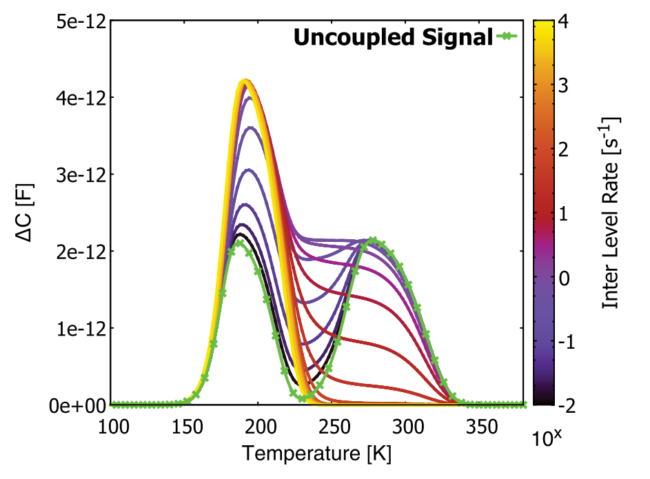
In this paper, a new versatile scheme to simulate DLTS signals was presented which allows an efficient but still flexible implementation and evaluation of physical processes that govern the coupling of the defect levels to the respective carrier bands. This can play a key role in understanding the electrical properties of extended defects.

Simulation reproduces some below effects:

  • Coupling of defect levels: Due to the spatial proximity of the bound impurities to the dislocation loop interactions between the defects should not be neglected.The results are shown in figure. High coupling strength leads to the absorption of the DLTS peak which is normally seen at higher temperatures and a broadening of the absorbing peak with simultaneous increase of its amplitude is observed.In the same way, the broadening of a defect level distribution in the band gap causes a broadening of the measured DLTS signal.

  • Impact of Coulomb energy on DLTS signal: The “Coulomb ladder” of energy levels results in a shift of the peak to lower temperatures similar to the case of distributed defect levels E_{T,i}.

Journal Club 137

https://doi.org/10.1016/j.nima.2018.04.051

This paper describe the study of point- and cluster-defects in radiation-damaged silicon. This is the summary:

  • A new method of analysing TSC (Thermally Stimulated Current) spectra was used to study the point - and cluster-defects in radiation-damaged silicon. The method based on the assuming: the ionisation energy, 𝐸𝑎, depends on 𝑓𝑡 (the fraction of filled point defects in the cluster), which can be described as 𝐸𝑎(𝑓𝑡) = 𝐸0 − 𝛥𝐸a. For point-defects VO𝑖, the value of 𝛥𝐸𝑎 is compatible with zero from fitting the TSC data. This confirms that VO𝑖 is a point defect, and also demonstrates the validity of the method for point defects. For cluster-defects, to study the dependence of the cluster formation on electron energy, the data for 𝐸𝑒 = 3.5, 6, 15, and 27 MeV after annealing for 30 min at 80 ◦C are analysed. A tendency towards a saturation of 𝛥𝐸𝑎 is observed. after a rapid increase with electron energy. This is taken as evidence for cluster formation above a threshold. To study the annealing of the clusters, the data for the irradiation with 15 MeV electrons and the conditions as irradiated and after isochronal annealing for 30 min between 𝑇𝑎𝑛𝑛 = 80− 280 ◦C are analysed. This paper provides two models to explain the above phenomenon. The two models are first order model and diffusion model. Finally, the paper simulates the diffusion model and estimates the 𝑇𝑎𝑛𝑛 dependence of the diffusion parameters and of the spatial spread of the point defects in the cluster.

Journal Club 136

https://indico.ihep.ac.cn/event/11467/contribution/5/material/slides/0.pdf The JC-136 paper introduces the usage, advantages of TRACS and some theory of the simulation. TRACS is a multi-threading software based on the Shockley-Ramo’s theorem to simulate non-irradiated and irradiated silicon micro-strips and pad detectors of complex geometries. It helps understand signal formation and charge collection efficiencies of arbitrary charge distributions.

  • Describe the state of art where TRACS is framed.
  • Describe the scope and operation modes of the software.
  • Explain the theoretical background of TRACS, mainly based on Shockley–Ramo’s theorem for the calculation of the induced current.
  • Numerical methods used to approximate the differential equations are explained and related with the code.
  • Introduce multithreading computation in TRACS.
  • Contain a comparison of TRACS to measured data.

Journal Club 135

https://indico.ihep.ac.cn/event/11467/

This paper describe the latest results of ATLAS b-jet identification performance and efficiency measurement with ttar events.

  • The identification of jets containing b-hadrons (b-jets) against the large jet background containing c-hadrons but no b-hadron (c-jets) or containing neither b- or c-hadrons (light-flavour jets) is of major importance in many areas of the physics programme of the ATLAS experiment, plays a crucial role in a large number of Standard Model (SM) precision measurements, studies of the Higgs boson properties, and searches for new phenomena.

  • The most impoartant feature of b-jet is that it contains a b hadron which has a long life time, with the help of inner detector of ATLAS, we can reconstruct the secondary vertex of the b-badron.

  • Several algorithms have been developed to identify the b-jet: – Low-level identifications: IP2D, IP3D, SV1, JetFitter – High-level identification: MV2 and DL1

  • Events are classifies into one signal region(rich in ttbar events) and 3 control regions(rich in background events)

  • Mimimum likelihood methos is employed to extract the b-tag efficiency in each pT region of the signal region,

  • The derived efficiencies from data and MC agree well, the scale factors are close to one.

Journal Club 134

https://indico.ihep.ac.cn/event/11423/contribution/11/material/slides/0.pdf The JC-134 paper describes the topic of Develop of low-energy X-ray detectors using LGAD sensor. This is the summary:

  • Hybrid detectors have not yet been applied to low-energy X-rays due to their noise.
  • However, LGAD maybe a good candidate to detect low-energy X-ray due to its internal gain.
  • LGAD microstrip sensors fabricated by FBK were wire-bonded to single-photon- counting and charge-integrating readout electronics developed at the PSI in order to characterize their performance for soft X-ray detection.
  • The results demonstrate the possibility of extending the minimal detectable energy of X-rays for PC and the single-photon resolution for CI microstrip detectors down to or below 2 keV.

JC133 - Effects of terrestrial tides on the LEP beam energy

https://www.mendeley.com/catalogue/effects-terrestrial-tides-lep-beam-energy/

The precise measurement of the mass and resonance width of the Z boson, which are two most fundamental parameters, plays important role in testing the standard model.

In the electron positron collider, the precise measurements preformed by fitting to the visible cross sections as a function of the centre-of-mass energy, which requires a precise knowledge of the beam energies with a precision of 20 ppm.

At this level, the effects of terrestrial tides must be taken into account, as introduced in the selected JC paper.

Although not discussed in the paper, there are also other effects that not negligible. First, the change in circumference correlates with the rainfall and lake level seasonally; second, there is electrical noise that caused by the departure of high speed train to Paris.

For the next generation electron-positron collider working as a Z factory, these effects must be taken into accounts.

Journal Club 105

https://indico.ihep.ac.cn//event/9864/

The JC-105 paper describes the topic of ttbar multi-differential cross sections where data sets were recorded by the CMS experiment in pp collisions at sqrt(s)=13 TeV.

1. Introduction.

  • ttbar is mainly created via gluon fusion at p-p collider, therefore, the information of cross section is deeply related to the PDF (parton distribution function) in the protons, as well as the strength of its coupling.

  • Top quark decays before the hadroniation, thanks to its heavy mass. However, calculating its mass from the decay products, originated from a W boson and a b quark, is only robust estimation. That is because the top quark has a color whereas the final hadrons are all color singlet.

  • Question from Xin: what does the “top quark pole mass” represent ?

    • A. The definition of the pole mass is that the mass term in the propagator, where the renormalization is applied.
  • There is lots of discussion on this pole mass, though. For example, it is not easy as the QED to deduce higher order correction, because of the strong coupling.

2. CMS ( The Compact Muon Solenoid )

  • At 15 meters high and 21 meters long, it really is quite Compact for all the detector material it contains.

  • It is designed to detect particles known as Muons very accurately.

  • It has the most powerful Solenoid magnet ever made.

3. Event Selection

  • Signals consist of two jets originating from b quarks and two leptons originating from W bosons. e+e-, mu+mu-, e+mu- and e-mu+ combinations are allowed in this analysis. The event reconstuction has been performed as normal. ( see the detail in the slide )

  • The single variable distribusions, PT(t), y(t) (=rapidity of top), M(tt), and Njet are shown and compared with Monte Carlo simulation results.

4. Results: differetial cross section

  • Cross section is obtained using so-called “response matrix” which converts the experimental raw results into that for full phase space at parton level. Then, the double-differential cross sections and triple-differential cross sections are deduced and compared with MC expectations. Especially, the data exhibit softer PT distributions than the theoretical predictions (MC).

  • Subsequently, simultanous fit results for PDF, the coupling constant (alpha), and the pole mass is shown at the end.

Journal Club 104

https://indico.ihep.ac.cn//event/9864/

Yuzhen has presented the JC-104 Paper “Technology developments and first measurements of Low Gain Avalanche Detectors (LGAD) for high energy physics applications”.

The talk had started with the introduction:

A new concept of silicon radiation detector with intrinsic multiplication of the charge, called Low Gain Avalanche Detector (LGAD). Difference between APD (Avalanche Photo Diode) and LGAD: low gain requested to detect high energy particles the possibility to have fine segmentation pitches thinner devices with the same output signal

Simulation: effect on geometry of electrodes, structure, doping

Measurement:

I-V, C-V of sensor for wafer uniformity

charge collection measurement irradiation/non-irradiation

effect of temperature and anneal

She has shown the Schematic diagram of the LGAD sensor. She showed the simualted effect on Boron Implant Dose by the graph. There was a graph on Structure of JTE and Field plate (See figure on Page-5). The measurements of the voltage capability beyond 1100V has been shown in Fig-6 and Fig-7 showed 1/c^2-V curves for a sampling of the fabricated devices. Each curve corresponds to similar samples located on the same wafer with boron implant dose=1.6*10^13/cm^2. Fig-8 showed the charge collection measurement for the collected charge and noise signal for two LGAD samples after Sr-90 source MIPs exposure. The comparison is with the response of a conventional non-multipying pad diode(2328-10). Fig-9 was showing the effect of temperature dependence of the multiplication factor. Charge collection response for a MIP has been measured at different operational temperatures. The expected signal for a standard 300mm-thick detector has been depicted with a dashed line to allow the comparison with a non-multiplying detector. The annealing effect has been shown in Fig-10 and Fig-11.

Questions:

Yuhang’s Question: In this paper :”The measurements were performed on the same device after subjecting it to progressively increasing neutron fluences. Before each measurement, the sample underwent 80 min annealing at 60 ℃.” In general, annealing reduces defects, why should they anneal and then measure after irradiation?

Answers: In my opinion, the annealing will partially recover the effect of irradiation.

Xin’s question: On the last page of the paper, why “The p+ concentration is affected (reduced) by irradiation” ? Answer: The irradiation will remove the implanted acceptors of the p+ section at the junction.

Ryuta’s Question: Here is my question on this paper: At page 4, a simple explanation on the temperature dependence of the gain is described as “ … since the impact ionization coefficients exhibit temperature dependence, becoming larger as the temperature is reduced [14]” I only have heard about this effect, but I do not know why it is? Could you find/give further explanation ? (of course, I could check the reference[14] or something else by myself but …)

Answer: We cna check the paper in the reference[TEMPERATURE DEPENDENCE OF AVALANCHE MULTIPLICATION IN SEMICONDUCTORS] for this explanation.

Ryuta has shown the abstract and the motivation for the next JC-105 Paper, “Measurement of tt normalised multi-differential cross sections in pp collisions t √s = 13 TeV, and simultaneous determination of the strong coupling strength, top quark pole mass, and parton distribution functions”.

Journal Club 103

https://indico.ihep.ac.cn//event/9864/

Gu Shan presented the JC-103 Paper “Evidence of a Resonant Structure in the e + e − → π + D^0D^*− Cross Section between 4.05 and 4.60 GeV”.

The talk had started with the introduction:

The Y(4260) was observed only in hidden-charm processes, while its mass is close to open-charm thresholds, studies of the open-charm production cross section in e+ 𝑒− annihilation will provide important information on its properties.

The production of 𝑒+𝑒− → 𝜋𝐷𝐷bar^* is expected to be strongly enhanced above the nominal D𝐷_1 (2420) threshold and could be a key for understanding existing puzzles with these Y states.

In this Letter, we report improved measurements of the production cross section of 𝑒+𝑒− → 𝜋+𝐷^0𝐷^∗− at center-of-mass energies from 4.05 to 4.60 GeV using data samples taken at 84 energy points with the BESIII detector.

She has shown the event topology 𝑒+𝑒− → 𝜋+𝐷^0𝐷^∗− in which 𝜋+ can be reconstructed and D^0 can be traced with K+𝜋- and D^*- can be inferred from energy-momentum conservation. There will be charge conjugate modes are implied, unless otherwise noted.

She has shown the fitting to the D^*- mass inferred by the invariant mass recoiling against the D^0𝜋+ system, RM(D0𝜋+). Further, calculation of born cross-section has been shown with ISR correction factor and the correction factor from vacuum polarization. Also, dressed cross-section has been shown in the plot(see figure on page-6).

Questions:

Yuhang’s Question: In FIG2,what’s meaning of the phase-space contribution?

Answers: For each energy point, we generate MC samples of the signal process according to phase space (PHSP MC). (In dynamical system theory, a phase space is a space in which all possible states of a system are represented, with each possible state corresponding to one unique point in the phase space. For mechanical systems, the phase space usually consists of all possible values of position and momentum variables. The concept of phase space was developed in the late 19th century by Ludwig Boltzmann, Henri Poincaré, and Willard Gibbs).

Xin’s question: For the paper in equation 2, could you explain what does the “dress cross-section” mean? Answer: 𝜎𝐵𝑜𝑟𝑛 is the observed cross section, when considering the correction factor for vacuum polarization, 𝜎𝐵𝑜𝑟𝑛 ×(1/|1−𝕀|)^2, it is the so called dress crosssection, 𝜎𝑑𝑟𝑒𝑠𝑠 .

My Question: what is R1 and R2 in Fig-2?Can you please explain Fig-2 a little bit? Answer: Two enhancements obtained from the fit result of the cross section.(see page-6 for the plot).

Ryuta’s Question: could you explain about the relationship of those ?

1) Y(4260) without open charm channel decay (==dip) and DD1bar(2420) molecule interpretation

2) observation of open charm channel (𝜋+𝐷0𝐷∗−) with Y(4220)? Answer: We didn’t observe Y(4260), it is just observed in the hiddencharm processes. DD1bar(2420) molecule model is proposed as an interpretation of the Y(4260). We observed the Y(4220) in this paper. She also referred some papers:

Phys. Rev. D 90, 074039 (2014)

Phys. Rev. Lett. 111, 132003 (2013)

Phys. Rev.D 94, 054035 (2016).

Yuzhen has shown the abstract and the motivation for the next JC-104 Paper, “Technology developments and first measurements of Low Gain Avalanche Detectors (LGAD) for high energy physics applications”.

Journal Club 102

https://indico.ihep.ac.cn//event/9864/

Suyu has presented her JC-102 Paper and the topic was “High-resolution three-dimensional imaging of a depleted CMOS sensor using an edge Transient Current Technique based on the Two PhotonAbsorption process (TPA-eTCT)”.

She introduced the TCT, which is a silicon detector by carrier generation using “picosecond laser pulses”. Single Photon Absorption dominated carrier generation is induced along beam path. Laser wavelength is “above Si bandgap” ( λ <= 1150nm). The TPA-TCT, only non-linear absorption is relevant.Femtosecond pulses are needed because TPA absorption probability is significant only for very short pulses. Laser wavelength is below Si bandgap( λ >= 1150nm ). Both have the advantage of good spatial resolution and large penetration depth. She had shown us about the experimental arrangement too that the 3-D scan can be realized by the boundaries of the sensitive volume located in the plane XY and also find the focus point in Z-coordinate.(See figure at page-3). Later she had shown us the experimental results with HVCMOS map and collection charge map and collection time map.

  1. Transient currents at each of these regions are compared.
  2. Time and charge can reflect the construction.
  3. Depletion thickness vs voltage.

So, she conlcuded her talk by saying that Dimension and geometry of the space charge region is measured, computing the effective doping concentration of silicon substrate.

Questions:

Yuhang’s Question: In this paper, it say:”The unprecedented spatial resolution of this new method comes from the fact that measurable free carrier generation in two photon mode only occurs in a micrometric scale voxel around the focus of the beam.” and “Very near infrared wavelengths (typically 1064nm) can be collimated to ∼ 5 μm over several mm depth but carriers are generated along the whole beam path lacking point spatial resolution.”Does this mean in TPA-TCT carriers aren’t generated along the whole beam path? Answers:In TPA, focused light generates photocarriers only in a localized volume around the focus. That’s the reason why it’s able to spatially resolve implants.

Xin’s question: The resistivity ρ of the bulk can be calculated by fitting the measured depletion to w(V) (μm) = 0.3 sqrt(ρ)V, could you explain the meaning?Then, what does the nominal 10Ω cm mean? Answer: As I personally think, \pho can be got by fitting as a parameter. Depletion width is 0.01mm, we can get \pho 15Ω by the equation.

Gushan has shown the abstract and the motivation for the next JC-103 Paper,Evidence of a Resonant Structure in the e + e − → π + D^0D^*- Cross Section between 4.05 and 4.60 GeV.

Journal Club 101

https://indico.ihep.ac.cn//event/9242/

Yuhang presented the JC-101 related to LGAD and the title was “Radiation hardness of gallium doped Low Gain Avalanche Detector”

He introduced that LGAD has n++-p+-p-p++ structure to achieve high enough electric field near the junction. The advantage of this kind of structure is that the timing resolution can be achieved to 26ps. But, there is problemwith this is that harsh radiation environment leads to decrease the gain. The reason behind the decrease in the gain is the acceptor removal in the multiplication layer and for this reason we can use gallium doping as gallium is more difficult to displace/dislocate from the lattice site than boron. The result of this doping was good and the removal rate of gallium was found to be 5*10^-16 cm^-2, around two times smaller than for so far studied boron LGAD detectors. This feature could lead to significantly improved performance of thin Ga-LGADs at HL-LHC.

He pointed out the Performance before irradiation: The process parameter for gallium implantation, unlike for boron, are are less studied abd known. As a result, the implantation profile of gallium differed from the planned one and this led to very high gain and consequently break down of the devices starting at around 30V with a steep rise of the leakage current. Also, there was a difference of around 25% between highest(Dose 4) and lowest(Dose 1)(see figure)

He showed the plots and made it clear that Ga-LGADs perform better in terms of charge collection when compared not only control/no-gain devices, but also better than similar B-LGADs. He also showed the gain plot of Ga-LGADs and it was clear that the stronger the irradiation intensity, the lower the gain is not necessarily.

The electric field model shows almost identical (similar positive space charge) in the detector bulk for the devices with LF doesnot equal to 0.

Questions: Amit’s Question: In point 3, Performance Before Irradiation: The process parameters or gallium implantation, unlike for boron, are less studied and known. As a result, the implantation profile of gallium differed from the planned one. why did they choose gallium if they didn’t know the process parameter of gallium? Was this a testing for gallium? Answer: The reason they choose gallium is that It was observed before that initial acceptor removal is smaller for gallium than for boron doped silicon after electron irradiation in solar cells. This was a test. Meanwhile, they don’t know the process parameter of implantation, but if the simulation is good, they can improve the process of implanation.

Yuzhen’s Question: In Section 4 “4. Charge collection and gain of LGAD devices “, can you tell us about how to test the LGAD gain? Answers:The gain can be obtained by the given formula mentioned in the talk.

Xin’s question: At the end of the paper, it says: “the concentration of gallium in the multiplication layer was too high causing an early break down of devices before irradiations.”, could you explain more? Answer: The break is when the bias voltage is greater than 30V, the leakage current is multiplied. Under normal circumstances, this value will be greater than 400V.

GuShan’s Question: What is the basis for the the multiplication layer to select dopants? Answer:1.Choose ⅢA as acceptor and form P-N junction with donor from periodic table. 2.ⅣA change the performance of semiconductors.

Suyu’s Question: Why could gallium mitigate the acceptor removal? Is there theoretical explanation? Answer: Answer: Gallium is heavier than boron and thus more difficult to displace from the lattice site and could be less susceptible to reactions with vacancies in the Si lattice (V) and interstitial silicon atoms (I).

Ryuta: Q. In page 1, the sentence, “Gallium is heavier than boron and thus more difficult to displace from the lattice site …” explains the motivation of the introduction of Gallium, as well as one of possible interpretation of the obtained results. Similarly, can we think about the indium (In) as the acceptor at the multiplication layer or not ? What would be different between Gallium/Boron and Indium ? Answer:Si-ln was used as infrared detectors. I think the ∆𝐸(Ec-Ev) is different between Si-Ga, Si-B, and Si-In. Others are not clear.

Suyu has shown us the next JC-102 Paper and the title was “High-resolution three-dimensional imaging of a depleted CMOS sensor using an edge Transient Current Technique based on the Two Photon Absorption process (TPA-eTCT)”.

Journal Club 100

https://indico.ihep.ac.cn//event/9242/

Xin has presented very interesting paper about “Seacrh for Scalor Dark Energy and mono-jet final states with the ATLAS detector”. He has started his talk with the introduction of Dark Energy:

Accelerated expansion of universe continues one of the biggest mystries in cosmology and particle physics. The First evidence comes from High-Z supernovae searches and supernovae Cosmology Project. He stated that Dark Energy is a new type of matter adn was added to explain the repulsive force in the context of GR. It was also corroborated by Cosmic Microwave Background (CMB) and large scale structure of the universe.

The Models to describe Dark Energy are:

Modification of GR Addition of new particles beyond the SM Models with extra fields can have the same phenomenology as modified gravity models. Cosmological observations alone not able to distinguish the two scenarios and Input from particle physics experiment is important for elucidating the microscopic nature of Dark Energy.

Direct and Indirect detection of Dark Energy:

Like Dark Matter searches by Direct and Indirect detection Method, also Dark Energy searches are ongoing by Direct and Indirect Methods. Some of the modes are Search for additional gravitational forces(“fifth force”)- deviation from inverse square law, search for photons produced by the interaction of DE with intense magnetic fields, direct detection of DE at colliders relies on the assumption of a non-zero coupling between th DE and SM fields, and essential ingradient for the screening of fifth force mediated by scalar DE fields.

In this direct search for DE at colliders, modification of electro-weak precision observables induced by virtual DE particles-found to yield very weak constraints on DE models through the direct production of DE particles.

Direct DE production is an effective way of detecting or constraining DE models- enhanced in final state with heavy quarks or high momentum transfer and certain types of couplings (disformal) of DE to SM matter cannot be constrained by local tests of gravity since they don’t generate fifth force.

further he presented the Lagrangian of Effective Field Theories for scalor DE and how it presents the kinetically dependent conformal and disformal(Mono-jet production).

Questions: Yuhang’s Question:In table.3, how to get the value of +1σ,-1σ? Answer: It depends on the signal production cross-section.

Shan’s Question: “What’s the commonly used methods for searching for the dark energy?” Answer: Already explained in the Introduction part of this talk.

Kai’s Question: The dark energy effect is observed at very large scale on the galaxies very far away, i.e., the galaxies are getting further with accelerated speed. But is there any evidence observed that our milky way galaxy, or even our solar system being expanded by Dark Energy? The Motivation behind this question is: If only the distances between galaxies are expanding, but galaxies themselves are not expanding at all, the density of dark Energy in our solar system/galaxy may be very very small. And considering that the amount of particles with similar or even higher energy in the sun/centre of the galaxy is far more than that production in the collider, I personally doubt the worth of searching dark matter in colliders.

Answer: The Dark Energy effect can observed by the expansion of the universe by looking the nearby galaxies through telescopes. It is confirmed that the galaxies are moving apart with an accelerated manner. But, We can’t assume that this effect will be present there in a galaxy to expand itself. If a galaxy is expanding (according to querry) then there would have not been enoguh matter available till now after big-bang and the disc would have been gone of a galaxy. Because of the presence of Dark Matter Haloes? in surrounding we can justify the galaxy rotation curve successfully. Yes, The density of the DE in the solar system/ galaxy is very very small and almost negligible.

Ryuta’s Question: Are there any indications on fifth force, or more specificly, on quintessence ? Answer: Presently no. There is no observation for such quintessence.

Suyu’s Question: How could dark energy be produced in collider? We use conservation of energy to constrain target particle. Answer: Missing Energy in the colliders like mono-jets can shed light. But, it is not well observed and still a long way to go.

Special Topic 63:

I have presented the Special topic “Tutorial on TTree and ROOT”.

I have presented the special topic data analysis using ROOT Tree. I have discussed the reading and writing and also defining tree in various formats. Later I have introduced about the TLorentzVector and it’s uses.

Yuhang Showed his JC-101 Paper “Radiation Hardness of Gallium doped low gain avalanche detectors” which he will present in next week’s meeting.
Journal Club 99

https://indico.ihep.ac.cn//event/9242/

Liu Kai presented an interesting paper named as “First Measurement of Form Factors of the Decay of charmed baryon into sigma and electron and anti-neutrino pair”. In the paper they have mentioned that from polrization measured with sigma baryon with the decay of sigma into proton and neutral pion and electron neutrino pair, the g1/f1 to be 1.32+-0.21(0.17)(stat)+-0.05(syst) assuming the SU(3) (flavour) values for g2/f1 and f2/f1. This decay mode is identical to the well measured beta decay, except that the valence d quarks are replaced by s quarks in the initial and final state baryons. In the limit of exact SU(3) (flavor) symmetry the only differences between these processes arise from the different baryon masses and Cabibbo-Kobayashi-Maskawa (CKM) matrix elements. Modifications to the strong interaction dynamics due to the difference between the d and s quark masses can modify the form factors from their SU(3) values.

Questions: Yuhang’s Question:what’s mean about “second class current “ in page one ? Answer: Kai explained an equation for G-Parity conservation in the SM.

Ryuta’s Question: It would be out of this paper but, is there any investitation/report on the stimation of this form factor ratio g1/f1 from the lattice calculation side? (possibly the precision would not be good enough but …) Answer: Kai has presented with different investigation from another paper. The effects of SU(3) symmetry breaking in HSDs were examined from lattice QCD.

Xin’s Question: In Eq.3, it introduced the “fictitious particle Q” , could you explain more? Answer: Kai pointed the reference to be studied for that, but also he mentioned that the transverse momentum of the neutrino is just equal and opposite the transverse momentum of the sigma baryon, we can obtain unambiguous angular variables transverse to the direction of charmed baryon momentum. This could be termed as fictitious particle Q.

Yuzhen’s Question:Could you introduce the details of SU(3)? Answer: Kai showed the picture of Hexagon.

Suyu’s Question: What are upstream and downstream? Answer: the lower part of the detector is called as downstream and the upper part is called as uptream.

My question: Why the SU(3) value has been shifted towards left from central value also the theoretical values? (Fig 3) Answer: The value is fixed at 1.32 and the maximum likelihood well set with theoretical prediction.

Special Topic 62:

Yuhang presented the Special topic “Radiation Damage in Si-Detector”.

There are mainly 2 types of radiation damage in silicon devices.

  1. Ionization Damage
  2. Displacement Damage (related to not-ionizing energy loss) The most important radiation damage is displacement damage: Defects created in the bulk form energy levels in the band gap: releasing electrons in the conduction band or trapping those from the valence band.Defects-related energy level in the forbidden band increases the generation/recombination rate, thus increasing the leakage current as well. Modification of the effective bulk doping: change depletion voltage and increase leakage current. The microscopic origin of the initial acceptor removal has not been fully understood yet, but experimental observations suggest the creation of acceptors ion complexes that result in the de-activation of doping elements, which are removed from the lattice by interstitials. Reduction of the charge collection efficiency: increase of defects-related trapping centers. Hence the longer the drift time, the higher is the probability that a carrier has to be trapped. In LGAD: This effect of initial acceptor removal not been understood yet. One Possible explanation: In irradiated Silicon with a fluence-dependent concentration that forms with Boron B-I complexes which are electrically inert. These complexes make Boron atoms inactive. To overcome this issue two researches came out: 1.The first one is to reduce the concentration of interstitials available for capturing B atoms by using Carbon-enriched Si wafers where the interstitials get filled with C instead of with B. 2.The second one is to reduce the formation of the acceptor-interstitial complex by replacing Boron with Gallium.

Xin has introduced the next JC100 paper of ATLAS Collaboration “Search for scalar dark energy in tt¯ + EmissT and mono-jet final states with the ATLAS detector”.

Journal Club 98

https://indico.ihep.ac.cn//event/9242/

I have presented the paper about Electromagnetic Dalitz Decay in which psi(3686) decaying into four leptons and J/psi in the final state. In this paper, the author has observed this type of decay first time. The study of ELectromagnetic Decays has been observed many times in light-quark meson sectors however, the analogous transition in charmonium decays have not yet been studied. BESIII experiment confirms that the contributions from the higher order multipole amplitudes in psi(3686)->gamma chicj are very small and E1 contribution is dominant. Therefore, it is a great interest to measure the EM transition of ψ(3686)-> e+e-χcJ and χcJ-> e+e-J/ψ.The EM Dalitz decays in charmonium transitions, such as ψ(3686)-> e+e-χcJ or χcJ->e+e-J/ψ, have access to the EM transition form factor of these charmonium states. The q^2 dependence of charmonium transition form factors(TFFs) can provide additional information on the interactions between the charmonium states and the electromagnetic field, where q^2 is the square of the invariant mass of the e+e− pair, and serve as a sensitive probe to their internal structures. The q^2-dependent TFF can also serve as a useful probe for exotic hadron structures based on different models. The analysis uses a data sample of 4.479*10^8 ψ(3686) events taken at a centre of mass energy sqrt(s)= 3.686 GeV collected with the BESIII detector. The fit results are shown in Fig. 2 and the corresponding signal yields are summarized in Table I. For the six observed decay modes, the statistical significance of the yields are all larger than 5 standard deviations. Xin has asked the question that how can we measure the yield larger than 5 sigma. I told him that I can be calculated by the ratio of yield and it’s uncertainty. Further in the paper the author has discussed about the systematic uncertainty aand their sources. I have summarized the talk and mentioned that this experimental work will spur new theoretical development on the use of charmonium Dalitz Decays to address questions such as nature of exotic charmonium. Questions: Xin’s Question: why the “q^2-dependent TFF” can be served as a probe for exotic hadron structures based on different models? Answer: EM Dalitz decays in charmonium transitions have access to the EM transition Form Factor(TFF’s). In other words, The transition states have the access to the EM TFF’s. The q^2 dependence of charmonium TFF’s can provide additional information on the interactions between the charmonium state and electromagnetic field, where q^2 is the invariant mass of e+e- pair, and serves as a sensitive probe to their internal structures. Furthermore, the q^2 dependent TFF can possibly distinguish the transition mechanism based on the ccbar scenario and also the other soultions which alter the simple quark model picture. Hence, the author claims that the q^2-dependent TFF can also serve as a useful probe fro exotic hadron structures based on different models.In the future, the intrinsic structure of X(3872) can be well extracted by coparing the experimental measurement of q^2 dependence of TFF with different model calculation. The nature of X(3872), namely, whether it is a compact charmonium, multiquark state with quark clustering, or hadronic molecule can possibly be disentangled by the q^2 dependence of its TFF. Yuhang’s Question: On page3, it says:” The unknown modes are simulated using the LUNDCHARM model.” What’s LUNDCHARM? How to filter out unknown parts from the generated cases or LUNDCHARM can only generate unknown cases. Answer: You have the answer in your second line of the question. Yes, LUNDCHARM is an event generator for J/ψ and ψ(3686) decay.The LUNDCHARM model can generate all the cases which are theoretically known. In the paper, they have only taken the unknown cases from this generator. Suyu’s Question: Her question was about the decay processes? Answer: They are analyzing cascade decay process and both have same final state. In the first manner ψ(3686)-> e+e-χcJ or χcJ->γJ/ψ secondly ψ(3686)-> γχcJ or χcJ->e+e-J/ψ.

Special Topic 61: Kai presented a very interesting paper of N.Cabibbo of “Semileptonic Hyperon Decays and Cabibbo-Kobayashi-Maskawa Unitarity”. He mentioned that it could be a good idea for search for new physics contribution for the estimation of uncertainty condition delta. In table-I the results from V_us analysis using measured g1/f1 values and it is nearly the same values with kaon decays and larger from the previous analysis in somewhat. The larger V_us value from hyperon decays beautifully satisfies the uncertainty constraint.

Kai has introduced the next JC99 paper “First measurement of Form factor”.

Journal Club 97

https://indico.ihep.ac.cn//event/9242/

Yuhang introduced that LGAD were designed for particle physics experiments, medical and timing applications.He further added that to study the radiation hardness of LGAD, several sets of diodes were irradiated with reactor neutrons, 192MeV pions and 800MeV protons to the same equivalent fluences and it was found that the gain decreases with irradiation, which was attributed to effective acceptor removal in the multiplication layer. Xin Asked why is the time ranging in nano-seconds instead of pico-seconds on page:3(b) plot in x-axis. Yuzhen replied that this could be the reason because the LGAD taken in this paper is thick and it takes time to reach the current(basically charge) carriers from cathode to anode ring.

Later in his slides Yuhang replied the answers asked by the group members by email: Suyu: Ques: In Figure 4 (a) & (b), I think the turning point from steeply rising to moderately rising locates on 100V. Why do they say “300 V is required to raise the electric field”? Speaker’s Thoughts(Answer): When the bias voltage is around 300V, the gain will not change much when the detector is affected by a small amount of irradiation or other factors. But if we use 100V, gain fluctuations will be very large.

Yuzhen: Ques: In Figure 4 (c) and (d), the indicated stages of signal are different between W7 and W8, especially the 1.)drift of electrons, why? Answer: There is an upper limit to the current generated by the electron drift in the non-multiplier region when U is certain. Because of the high gain of W8, the voltage in the non-multiplier region is relatively low, and the current rises slowly, the current is easy to reach the upper limit.

Amit Pathak: Ques: In the section: 3.2 Irradiated Samples, The dependence of charge collection on fluence is shown in figure 6. Samples from both wafers were irradiated with neutrons. Selected samples from W8 were irradiated with 800 MeV protons and those from W7 with 192 MeV pions. In the Picture Description: 6, They have irradiated W7 wafer with neutron(Picture 6a) and pions(Picture 6b)(Energy 192 MeV) but in the case of W8 wafer with neutron(Picture 6c) and protons(Picture 6d)(Energy 800 Mev). Why are there two different energy scale to compare the dependence of charge collection on fluence? Answer: Pointed about this question that The fluences of particles were scaled to 1 MeV neutron equivalent fluences by using hardness factor: 0.92 for reactor neutron(>100keV) and 1.14 for 192MeV pions and 0.71 for 800MeV protons.

Shi Xin: Ques: On page 7, it says about the reason for gain degradation: “The reason must therefore be related to the decrease of the multiplication gain rather than trapping of the drifting charge”. How to draw this. Conclusion? Answer: The relative decrease of measured charge is much more pronounced for LGAD than for standard devices (see figure 7 of the paper). The difference between LGAD and Fz-p is the multiplication gain.

Ryuta: Q: About Fig.11, what is the meaning of Vmr ? Especially, why the curves start to rise up from certain values (=Vmr) ? and the degreasing of Vmr toward 0V might indicate what ? Answer: Vmr is depletion voltage of p+ layer. The value of Vmr is is determined by doping concentration in p+ layer. When Vmr toward 0V, the gain is 0, and there is no multiplier layer.

Author also compared the results of measured induced currents after back illuminium in the LGAD irradiated to phi{eq}=2*10^14cm^-2 from W7 and W8.

Summary was the gain of the devices decreased fast and almost vanished at irradiation of 10^15cm^-2. The decrease of the gain after irradiation was attributedto removal of acceptors in the p+ layer. The removal was faster for charged hadrons. The leakage current increased due to linear increase of generation current with fluence, but was moderated by the decrease of multiplication.

Special topic60:

The Author presented the basic idea of his learning for python programming language. She has started with basic grammar of python with List and Dictionary and later with continue and break statements Later she explained the functions in python by explaining with suitable examples how to define a function and how to import tools. She also explained how to read a file and write a file in python language. Python is very efficient and powerful programming language among all the langauges and it was a very introductory topic for all of us.

Amit Pathak introduced the next JC98 paper with psi(2S) decaying into 4-leptons and J/psi.

Journal Club 93

https://indico.ihep.ac.cn//event/9242/

First,Amit introduced Search for Invisible Decays of a Dark Photon Produced in e + e − Collisions at BABAR. Next, Amit answered some questions.

Kiuchi: : Q. At the very begining, one of motivation of the dark photon search is described as “models attempting to explain certain astrophysical observations [1-4]”. Could you introduce one(or some) of these astrophysical observations, especially how we can interprete the results to the dark photon (excess of e+/e- events ?) ? Answer:We can discuss about this Fermi-LAT paper.

Xin:In the paper, it says: “These limits assume that the dominant decays of the A0 are to the visible SM particles, but are not valid if there are low-mass invisible degrees of freedom. Could you explain a bit more?

Answer:For this answer, I need to read the reference paper 8-16. There are constraints on invisible decays of the A0 from kaon decays [17–19] and from the recent search for missing energy events in electron-nucleus scattering [20]

Yuhang:In fig.3,Why use the Mx2 on the Horizontal axis, not Mx? Is there any special physical meaning?

Shan:In the sentence “we assume that a single A0 state exists in the range 0 < mA0 ≤ 8 GeV,” What is the basis for this energy interval setting? Next,Kai introduce selected highlights on the previous BESIII Collaboration meeting. Finally,Amit introduced the motivation about next JC paper.

Yuzhen:In Fig5, what is NA64? Is it an experiment? can you introduce some? Answer: NA64 is an experiment at the CERN SPS.

Next, Yuhang introduced μS+B fit. The main content include process,likelihood fit principle,fit method, and fit result.

Journal Club 92

https://indico.ihep.ac.cn//event/9242/

First,Yuzhen introduced Wire Bonding on 2S Modules of the Phase-2 CMS Detector .Next,Yuzhen answered some questions.

Kai:on page 12, the author introduces the three phases of the welding. the temperature increase is mentioned in all the three phases. Does the temperature increase being performed on purpose in order to keep the bond machine in a good working status, or , it is just some by-product in the process? Anwser: Increase temperature to make the wire meld to fix onto the surface.

Amit:: On page- 50, The BPC-slope is defined in the way that slope below 45◦ is result in too low wire deformation values, which leads to an error stopping the machine. On the other side higher bond times should be preferred. Thus, BPC-slopes of the order 50◦ to 60◦ are reasonable setup values. In figure 3.41, it is clear that the slope is more than 45◦ . Why does the high wire deformation good and low wire deformation cause to stop the machine?

Kiuchi: : Is there any works (or ongoing plans) to develop tools, like simulation, that can predict the parameters within certain range ? Anwser: don’t know very clearly. We use some experiential law and initial/default value when optimize the parameter.

Xin:In the summary (p79), it says “usually, the value of the touchdown force can be set to be the same as for the bond force”. What’s the difference between these two forces? Answer:The first connection point is made (picture 1) by moving down the bond wedge onto the bond surface and applying a well-defined force which in this thesis is called touchdown force (TDF) to achieve a pre-deformation. Then (picture 2) the US power is activated while a force is still applied to the wire. This force is called bond force (BF).

Yuhang:In fig3.1, how to tear off the wire? Anwser close the clamp

Shan:Knowledge about the LHC and CMS. What determines the luminosity of a detector? Answer:For my understanding, the luminosity is determined by the accelerator. Maybe some factors will affect the luminosity, such as types of particles, energy of particle, types of collider (circular of linear), cost of construction and technique of magnet et al.

Next,Kai introduce selected highlights on the previous BESIII Collaboration meeting. Finally,Amit introduced the motivation about next JC paper.

Journal Club 91

https://indico.ihep.ac.cn//event/8183/

First,Suyu introduced Beam test results of a 16ps timing system based on ultra-fast silicon detector. The main content included introduction,Properties of thin UFSD and Beam test results.Next,Suyu answered some questions.

Amit:What is the meaning of Constant Fraction Algorithm/Constant Fraction Discriminator(CFD)? Can you explain the Fig. 7 because I read in the paper it is somehow related with CFD? Answer:Take sigma as time resolution.

Kiuchi: Description of the event selection (left bottom of p4) briefly explains that “To eliminate the contributions from non-gain events, the time of the pulse maximum has to fall into a window of 1ns. “ Answer:Do you know/find distribution of “the time of the pulse maximum” from the other references ? ( Apart from this specific question, I somtimes wonder how we can effectively separate these two kinds of signals,one which passes trough the multiplication layer, and the other one )

Xin:In the last section, it says 3 planes of UFSD sensors reaches the expected performance improvement given by multiple measurements, i.e. the resolution improves like 1/sqrt(N). Could you explain why?

Yuzhen:In Fig.6, the Landau MPV and Gauss Sigma increase as the gain (or bias voltage) increase, but why does not the Landau Sigma increase with gain (or bias voltage) ?

Yuhang:What is the main reason for UFSD to achieve better time resolution than TOF? Material? Structure? Answer: Much closer to interaction point. And I think semi-conductor can behave better than PTM.

Shan:Can you briefly introduce “multiple sampling techniques”? Answer:https://ac.els-cdn.com/S0168900216308373/1-s2.0-S0168900216308373- main.pdf?_tid=9d1b7697-93f9-4f71-9fa3- 232ec6f28cf4 acdnat=1545975846_037f7cc20cfc9ca48b295472f0f16cbe for more information.

Next,Yuzhen introduce Alice ITS HIC production at PLAC (Pixel Lab At CCNU) . The main content contained Alice ITS Upgrade, Alice ITS Production, Alice ITS HIC production tips. Finally,Yuzhen introduced the motivation about next JC paper.

Journal Club 90

https://indico.ihep.ac.cn//event/8183/

First,Ryuta introduced Measurement of the Negative Muon Anomalous Magnetic Moment to 0.7 ppm. Next,Ryuta answered some questions.

Kai:Why they use values of proton in this analysis, such as NMR frequency ¥omega_{p}, and the magnetic moment in ¥lambda Anwser: wp is related to the measurement of B-field, which is measured/calibrated by NMR using proton

Amit:Why is the filed focusing index n is so important? because by changing it’s value, also reduced the correlation between the CBO and detector gain effects in the fits to the time spectrum.

Kiuchi: Could you explain the relationship between the Gain and the doping density or the electric field ? From this point of view, how we can very roughly understand the Fig4.and Fig.10 ?

Xin:The dependence of !a on the electric field is eliminated by storing muons with the ‘‘magic’’ gamma? Why this gamma is “magic”? Answer:Precisely determine w & B is essential ! but, the systematics are considered since the beam momentum has distribution

Yuhang:In Fig.2.What is the meaning of using high-n and low-n?

Shan:How to determine the initial value of the N0,A and phi_a in Equation 2 ? Answer:This represent the modulation. It is explained that the fitting is done by 5 free parameters

Next,Suyu introduce TOF sub-detector.Finally,Suyu introduced the motivation about next JC paper.

Journal Club 89

https://indico.ihep.ac.cn//event/8183/

First,Yuzhen introduced Low Gain Avalanche Detectors (LGAD) for particle physics and synchrotron applications. The main content included LGAD Concept,LGAD Simulation and Device Characterisation.Next,Yuzhen answered some questions.

Kai:From Figure 6, we indeed could get the conclusion that the breakdown voltage increased obviously with the JTE. But for me, the difference between simulation and measurement for cases with JTE (orange, and green lines) is about 200V, seems not that small, why they say: The fabricated results show reasonable agreement with simulation for the breakdown voltage. what kind of difference could be called unreasonable?

Amit:What is the meaning of Qeffective? Is these any relation between Qeffective and Gain?

Kiuchi: Could you explain the relationship between the Gain and the doping density or the electric field ? From this point of view, how we can very roughly understand the Fig4.and Fig.10 ?

Xin:On Fig. 5, are there any reason for the electrical peak near 35um?

Suyu:What’s the noise floor? Is it just a threshold?

Yuhang:In page1.How to detect low energy X-rays with hybrid pixel?

Shan:Can you explain “gain” in this paper? What does its level mean? Answer:the ratio of output to input signal.

Next,Amit introduce Hardware under BESIII detecter . The main content contained Drift Chamber, Time of Flight, Electromagnetic Calorimeter,Muon Chamber and Superconducting Magnet. Finally,Ryuta introduced the motivation about next JC paper.

Journal Club 88

https://indico.ihep.ac.cn//event/8183/

First,Kai introduced measurement of e+e- -> Ds+ Ds- cross sections near threshold using initial-state radiation. The main content included event selection and cross section.Next,Kai answered some questions.

YuZhen:What is the difference of D+* and D+? Answer:spin of the quarks are different, leading to difference in mass, spin-parity, etc.

Amit:On Page:- 4,The following sources of background are considered.Point: 3 - The low momentum gamma photon is not reconstructed and Point: 4.The pi0miss is not reconstructed.I just want to know, why?Is this reconstruction not in the MC simulation or not in the data? Answer:

Ryuta:The cross section of ee->DsDs seems to be one order lower than ee->DD, however, this paper describes (in the page 1) the one of motivations as “The Y states, ,,, provide additional motivation to pursue all possible experimental information about the decomposition of charmed particle production in the charm-threshold region” . This description is fine, but thereafter, is there some discussion/paper on Y states (or anything else) where the information of ee->DsDs result is effectively used ?

Xin:On page 5, it says “The contribution of final state radiation is strongly suppressed …”, could you explain why? Answer:FSR is dominated by photons collinear to the final-state particles while ISR is dominated by photons collinear to the beam direction.This suggests that we should consider only events with photons well separated from the charged from the charged final-state particles and preferentially close to the beam.

Suyu:For the sidebands selection, they used 4 times as large as the signal region, 60MeV, and divided it into windows of the same width as that of the signal, 30MeV. Then they shifted the sidebands, to avoid signal oversubtraction, by 30MeV from the signal region.From my point of view, 2 sidebands have same parameters of course, e.g. c0, c1. Does it means that they exchange 2 sidebands(move sideband above the Ecm to lower energy side, and another lower than Ecm to higher energy side)? Anwser:Don’t know how to shift the sideband.

Yuhang:On page 3,To suppress backgrounds two cases are considered.1)the γISR is outside of the detector acceptance and the polar angle for the Ds+Ds- combination in the c.m. frame is in the arange|cos(θDs+Ds-)|>0.9;2) the γISR is within in the detector acceptance |cos(θDs+Ds-)|<0.9.How to understand this. Answer:momentum conservation.the ISR and the (Ds()Ds()) system should be back to back.

Shan:What is the advantage of BESIII compared to Bell in searching for the XYZ states? Answer:many advantages:directly producing Y states – larger data sample[ main challenge from BelleII ] – precise measurement of state parameters – not only simply observe many many new states, but build the connections between them!

Next,Shan introduce XYZ States at BESIII. The main content contained the X state,the Y state,the Z state and summary. Finally, Yuzhen introduced the motivation about next JC paper.

Journal Club 87

https://indico.ihep.ac.cn//event/8183/

First,Yuhang introducedH→ e+e− at CEPC: ISR effect with MadGraph. The main content included CEPC basic information,Motivation,Signal and background,Cut condition,Calculate upper limit.Next, Yuhang answered some questions.

YuZhen:In Figure2, why does the curves decrease suddenly at about 250GeV? Answer:The center of mass energy is 250GeV.

Amit:How will the MADGRAPH change the effect of ISR in this analysis? Answer:MadGraph is a simulation method, and it can simulate e+e- ->ZH with ISR and without ISR respectively. I don’t know how to use MadGraph.

Ryuta:The ISR implementation in MadGraph is the title in section 2, but, could you briefly introduce the “Whizard” , “MadGraph” and their relationship ? Answer:MadGraph5_aMC@NLO is a framework that aims at providing all the elements necessary for SM and BSM phenomenology, such as the computations of cross sections, the generation of hard events and their matching with event generators, and the use of a variety of tools relevant to event manipulation and analysis.-High precision simulation WHIZARD is a program system designed for the efficient calculation of multi-particle scattering cross sections and simulated event samples.

Xin:In the page5, it says “ the 95% confidence level upper limit on H −→ e+e− branch ratio can then be decided to be 0.024%.”, it looks the 0.024% is an output value from the calculation. But why on page 6, Figure 4, in the caption, it says “assuming” the BR = 0.024%? Suyu:It says that ‘The 95% confidence level upper limit on H->ee can then be decided to be 0.024%.’ Could you explain the process in which they get the result? Answer:1.Get the distribution of 𝜇 which obey Gaussian. 2.Get the 95%CL upper limit of 𝜇. 3.Get the 95%CL upper limit of signal branch. 4.Use the 95%CL upper limit of signal branch to fit ZH_inclusive.

Kai:Last line of page4, 50000 signal generated and final efficiency about 7%, this will give a yield about 3500, but only about 20 in Figure 4, what’s the reason? Answer:Generate 10^6 Higgs. BR(H->e+e-)=0.024%. The number of H->e+e- generated is 240. The efficiency of selecting is 7%. So the number left is 7%×240=17.

Next,Yuzhen introduce What is plasma?. The main content contained Plasma,Plasma processing fundamentals: frequency and others,Low pressure gas plasma diagram ,Plasma cleaning in wedge bonding and March plasma systems. Finally, Liukai introduced the motivation about next JC paper.

Journal Club 86

https://indico.ihep.ac.cn//event/8183/

First,Gushan introducedmproved measurements of 𝜒𝑐𝐽→𝛴+𝛴-−and 𝛴0𝛴0 decays.Next,Gushan answered some questions.

Yuhang:In TABLE II,the theoretical value is far from the measured value in χc0->Σ+Σ- channel. In summary ,it also say:“The results for χc0 ->Σ+Σ- and χc0 ->Σ0Σ0 are still inconsistent with the prediction.” What caused this result? Answer:𝜒𝑐0 → ΣΣത is supposed to be highly suppressed by the helicity selection rule. However, J. Phys. G 38, 035007 (2011) results indicate that the transitions via these kinds of loops as longdistance effects can give significant contributions.

Amit:Can you please explain what is Helicity Selection Rule with a suitable example? Answer:Briefly introduce it.

Ryuta:In the Fig.4 (left), the invariant mass of Sigma+/Sigma-, I could find a small bump-like structure around 3.36-3.37 GeV. If I check that for the case of Sigma+/Pbar/K0short, as you have shown last week, there also would be a similar structure on this region. Answer:No discussion on this.

Xin:Could you briefly explain what is the “color octet mechanism (OCM)” ? Probably with Feynman diagram … Answer:It’s a model in the Non-relativistic Quantum Chromodynamics,(NRQCD), it is used to deal with the decay of the colored heavy quarkantiquark pairs on the short and long distance scale problem.

Yuzhen:In Fig.3 (left), the density of black point in the center is highest, but density of up, underneath, left and right side of the center is a little higher than other places, why? Answer:1, He has selected the clean Λ signals. 2,The width of Λ is very narrow.

Suyu:In right panel of figure 1, what’s the rule to select such the boxes as background? As I remember, you did some similar thing in your analysis. Why some box contributes as 1/4 while others 1/2?

Kai:section V, the PDF of signal peaks including a Gaussian function, why the mean value is set to be zero? Anwser:Actually, if we didn’t set it to be zero, the mean of the shape will shift because of the convolution. Usually we will set it too. otherwise it will give a very small change interval

Next,Liukai introduced Introduction to technical documentation. Finally, Yuhang introduced the motivation about next JC paper.

Journal Club 85

https://indico.ihep.ac.cn//event/8183/

First,Suyu introduced Teambeam Studies with Silicon Strip Module Prototypes for the ATLAS-Detector towards the HL-LHC. The main content included Module Prototypes,Sensor and reference,Sensor and reference.Next, Suyu answered some questions.

Yuhang:In figure 1, what‘s the effect of the Cooling Box? The modules have been tested in operation with various temperatures, how to control the temperature? Answer:Control temperature by DCS(more details can be found in my special topic last Friday).

Amit:I didn’t get the essence of adding the pixel sensor (FE-14) between the planes of telescope only at one side? Answer:Used as reference plane

Ryuta:At the begining of Section 6., there is a statement of “In a first step, the noise of the modules at a charge deposition of 1.5fC has been calculated using a responce curve(RC) measurement …” Answer:What is the meaning of this sentence ?

Xin:What’s the meaning of “Noise Occupancy” in this context? And its relation related with Vth (threshold) in Fig. 5 ? Answer:1)Probability of having a hit on a strip caused by noise 2)With Vth going higher, noise & efficiency go lower.

Shan:In figure 5, what’s the relationship between two vertical axes(efficiency and Noise Occupancy)? Answer:With Vth going higher, noise & efficiency go lower

Next,Yuhang introduced Quantum sensors. The main content contained the principle of quantum sensors and atomic clocks. Finally, Suyu introduced the motivation about next JC paper.

Journal Club 84

https://indico.ihep.ac.cn//event/8183/

First,Xin introduced a new era in the search for dark matter. The main content included a growing sense of “Crisis”,the fall of natural WIMP,alternatives to natural WIMPs,probing DM with astronomical,gravitational wave portalobservations and the future.Next, Xin answered some questions.

Next,Suyu introduced the HGTD Testbeam in CERN. The main content contained 2018 program,testbeam equipment,basic setup,sensor setup with box open,and what should I do as a shifter? Finally, Suyu introduced the motivation about next JC paper.

Journal Club 83

https://indico.ihep.ac.cn//event/8183/

First,Amit introduced Observation of the Z → ψl+l− Decay in pp Collisions. Next, he answered other’s questions.

Kai: This paper only shown the invariant mass distributions for the psi muon pairs and psi lepton pairs, but they do not show plots for the other leptons. how to get the conclusion that the other leptons from Z, not from other intermediate states from Z?

Answer: Because of the short life-time of the tau particle, it promptly decays once produced. Hence, it is very difficult to construct Z boson decay with tau lepton than other leptons such as electrons and muons.

Yuzhen: Why the author can get sin2(ϴ23) and ∆(m32)2 from the observed number of e neutrino and anti-e neutrino?

Answer: “Fits to determine either one or two of the oscillation parameters are performed, while the other parameters are marginalized”.Sinθ13 is fixed for this fitting, though I could clearly confirm that the δCP is fixed, (or less effect ?)

Xin: Based on the Fig.1 Feynman diagram, how to derive the gamma *–V transition strength from the measured V → l+l− electromagnetic decays?

Answer: It’s a theoretical question and I can’t give this answer for now. I will have to read more about this.

Yuhang: The probability density function (pdf) of signal is a sum of four terms, each of which is a yield parameter multiplying a component pdf. How to use the four terms account for four different backgrounds?

Answer: The four terms account for the z->psil+l- signal and the backgrounds from Z->l+l- accompanied by nonresonant mu+mu-, nonresonant Jpsil+l-, abd nonresonant mu+mu-l+l-. I didn’t understand too?

Shan: In this sentence: the experimental efficiencies to reconstruct events within the fiducial phase space are determined from simulation; combined with the trigger efficiencies given above they are 81%,80%,81%. Why thest efficiencies are so high?

Answer: As far as I think for these high efficiencies because they have a seperate muon chamber in CMS. Like in BESIII we have muan detection chamber at the outer surface of the detector. So, muons can be detected at both the places.

Suyu: Why is J/psi required from psi(2S)?

Answer: Maybe we can’t distinguish between J/psi and psi(2S).

Ryuta: How we can interpret the obtained value R (=0.67+-0.18+- 0.05) itself ?

Answer: I can not say you more about these limits for the branching fractions as I need to know more about these techniques.

Next,Ryuta introduced the topic around plasma acceleration. The main content contained gradient of RF cavity、advanced WAKEfield Experiment、steps toward the electron acceleration and the comment.

Finally, Xin introduced the motivation about next JC paper.

Journal Club 82

https://indico.ihep.ac.cn//event/8183/

First,Ryuta introduced the search for CP violation in Neutrino and Antineutrino Oscillations by the T2K experiment. Next, he answered other’s questions.

Kai: Mass ordering is important parameter in CP violating phase determination, and in the paper, they indeed considered two assumptions on the mass orderings, normal ordering, inverted ordering. But why they only report results of normal ordering in the abstract, do you know the reason?

Answer: Actually, I do not know…As pointed out, the derived values for both normal/inverted ordering are described in the contents/conclusion

Yuzhen: Why the author can get sin2(ϴ23) and ∆(m32)2 from the observed number of e neutrino and anti-e neutrino?

Answer: “Fits to determine either one or two of the oscillation parameters are performed, while the other parameters are marginalized”.Sinθ13 is fixed for this fitting, though I could clearly confirm that the δCP is fixed, (or less effect ?)

Xin: At the end of paper, it says: “Sensitivity studies show that, if the true value of δCP is −π/2 and the mass ordering is normal, 22% of simulated experiments exclude δCP = 0 and π at 2σ C.L.”. How to extract the 22% value? And why use 2-sigma C.L. ?

Answer: This sentence is not clear for me, especially what parameters they changed in the simulation and/or they want to express that there exists systematic terms not well implemented ?

Yuhang: In fig 2. Ratios to the predictions under the no oscillation hypothesis are shown in the bottom figures. How to understand the ratio?

Answer: υμ/anti-υμ disappears due to the oscillation(υμ flavor is mainly changed to υτ ).The energy of υμ is about 600MeV, therefore, it would be rare to create τ from υτ.

Shan: What’s the “2p-2h” model, also the 1p-1h, ∆-like 2p-2h and non-∆-like 2p-2h ?

Answer: “2p-2h” model is the scattering of W boson with two nuclei.Model to consider the interaction of W boson with the nuclei in higher order.

Amit: What is the meaning for delta-Like and Non-Delta Like?

Answer: Difference is the model of those reactions . ( though I do not cover them well )

Finally,Xin introduced a new software-GanttProject. This software may improve capable to deal with management complexity.

Journal Club 81

https://indico.ihep.ac.cn//event/8183/

First,Suyu can’t join this meeting, we scaned her slides about design and fabrication of an optimum peripheral region for low gain avalanche detectors briefly. Next, we saw other’s questions and she answer.

Kai: In the recent jc papers about low gain detectors, the value of gain ~10 appears very frequently. Is there any special reason for this value of 10? Is it just a balanced value that neither too large nor too small to test the equipment. is the gain the lower the better? Answer: No special reason. It depends on the signal-to-noise ratio. The moderate increase can lead to a notable improvement of the signalto-noise ratio.

Ryuta: What kind of noise is expected for the high gain case by which the parallel noise becomes important, that is not the case for the “moderate” gain ? Answer: I think the conclusion coming from experimental results, but I don’t know the theory.

Xin: In the end, why “The use of a different dielectric on top of the peripheral region with reduced or even negative charge density could enhance the detector performance without using any additional P - type diffusion at the peripheral region.” ?

Yuhang: Junction Termination Extension is a technique for increasing avalanche breakdown voltage and controlling surface electric fields in P-N junctions. But the extension of the shallow N+ diffusion does not provide a high breakdown voltage, the relationship between Junction Termination Extension and Deep N-type diffusion. Answer: If you’re asking the what the relationship between them is, I would say that Junction Termination Extension is just a kind of technique for us to get deep N-type diffusion.

Finally,We saw Yuzhen’s slides. She introduced Wire bonding test. The main content is commonest application、principle (test speed)、tool alignment、tool materials and pull test failure modes.

Journal Club 80

https://indico.ihep.ac.cn//event/8183/

First,Yuzhen can’t join this meeting, we scaned Ultra-fast silicon detectors briefly. Next, we saw other’s questions and she answer.

Suyu: How can we get the characteristic trapping time if we know a trapping length? Answer: For my understanding, trapping length is relative to the thickness. Trapping time is the collection time, it is the test result. Or using the charge particle dynamics in electric field..

Amit: I just want to know a better explanation for figure 9A.I have searched about the Weightfield2, which is a software for 2D simulation for silicon detector. But I want to know about BD3 big 35pF, SD2 small 2.6pF,WF2_big and WF2_small and how they show the gain of 3.5 with the alpha particle injection? Answer: For my understanding, adjust the bias voltage to change the gain.

Kai: Since present experience with LGAD is limited to sensors with 300 μm thickness[4], a reliable tool is needed to extrapolate their performance to the planned thickness of 50 μm. why the thickness is so important? Answer: Thickness affects the running time of the electron and hole, thus effect the charge collected time and shape of LGAD pulse. There are concerned to the time resolution.

Ryuta: Broad-Band amplifier (BB) is emphasized many times throughout this paper, but what is the BB ? (actually, it remind me the other amplifier, CSA, though I’m not quite sure for both) Answer: Broad band amplifiers are amplifiers which will reproduce a wide range of signals without significant loss throughout the pass band. (I am also not so clear about BB) CSA is charge sensitive amplifier, the output is proportionate to the input charge.

Xin: Could you elaborate the two proposed reasons for the gain degradation in LGAD devices? Answer: In actual, don’t know. Sorry.

Yuhang: There are several analysis algorithms to optimize the time resolution. what’s extrapolation of the slope to the base line and constant fraction discriminator(CFD), in fig.6 the meaning of CFD%. Answer: Some picture to explain the question.

Finally,Yuhang introduced Frequentist statistics briefly in special topic.

Journal Club 79

https://indico.ihep.ac.cn//event/8183/

First,Ryuta introduced gain homogeneity and radiation effects of Low Gain Avalanche Pad Detectors briefly. Next, he answered other’s questions.

Xin: Could you elaborate the two proposed reasons for the gain degradation in LGAD devices? Ryuta: Measurements on LGAD samples with leakage current in the range of few μA showed that the voltage needed to deplete the multiplication layer after irradiation decreases. This effect was associated with an acceptor removal due to the removal of boron in the multiplication layer which would also explain the observed gain degradation. An alternative explanation for the gain degradation in LGAD devices is based on the simulation of LGAD structures which showed that the effect could be caused by charge trapping in the device.

Yuhang: The reason about comparing the results for neutron and proton irradiation but also with previous measurements in the fluence range below 10^15 neq/cm^2 showed that the effective acceptor removal works faster for charged hadrons. Ryuta: This is one of hot topic for the study of radiation damage, and one of summary of this paper.

Suyu: We can easily see the influence on the gain of the devices, but what can we learn for intrinsic charge multiplication? Ryuta: From the histograms in the paper, the decreasing of the gain by the multiply layer & the other part is not clearly separated.

Amit: What is the guard ring structure in the design and why due to the absence of a guard ring structure in the design, it is impossible to distinguish surface from bulk current contribution? Ryuta: I was trying to find out the schematic for the guard ring … any rate, Guard Ring locates around the peripheral position.

Kai: In Fig2., what caused the left side of the signal increased more sharply compared with the righthand side? it seems more clear on plot (b), and there’s a small tail on the right side. Ryuta: Maybe, the total amplitude (by the multiply layer) as well as the enhanced E-field.

Finally,Gushan introduced first measurement of𝝌𝒄𝑱 → 𝜮+𝒑𝑲^𝑺𝟎+𝒄. 𝒄(J=0, 1, 2) decays. The main contents are data sets, event selection, background analysis, systematic uncertainties and summary.

Journal Club 78

https://indico.ihep.ac.cn//event/8183/

First,Yuhang introduced Cross section and Higgs mass measurement with Higgsstrahlung at the CEPC. He answered some questions from others.

Suyu:What’s Higgsstrahlung ? Yuhang:Higgsstrahlung is the process about e+e–>ZH.

Ryuta:What’s the cuts effect and meaning. Yuhang:The cuts which suppress the 2 fermion backgrounds is coming from the total momentum is zero and two moun’s angle are about 180 degree.

Xin:Why is impossible for the LHC to access the Higgs total width or absolute couplings in a model-independent way? Yuhang:Precision tests of higgs boson couplings to one-percent will require complementary precision programs. Because the model is depandant, the precision cannot be trusted. Absolute couplings and in a model-independent way. Xin:The reason of impossible may be that we cann’t mearsure all branches ratio about higgs decay. So we don’t know the total width.

Next,Ryuta gave a brief introduction about next JC topic.

Journal Club 76

https://indico.ihep.ac.cn//event/8183/

First,Kai introduced observation of the decay D0→K-π+e+e-, and answered Gu’s question about FCNC.Below are detailed questions and answers. Xin’s question:Does this veto those BSM predictions.

kai answered:uncertainties in theoretical predictions are large.The BSM predictions not been ruled out.

Suyu’s question: why do they treat the uncertainty in branching fraction as a independent one?

kai answered:For the external uncertainty,the results could be update conviniently.

Finally,kai put forward his doubt about whethe this decay is a FCNC process. Second,Ryuta introduced the Higgs couplings.He told what is Higgs coupling ,which precision on the measurement of the couplings,and How to measure the couplings.

Third,Xin maked a simple introduction about next JC paper.

Journal Club 75

https://indico.ihep.ac.cn//event/8183/

Shan_Gu introduced precise measurement of e+e-→π+π-J/ψ Cross Section. She answered Xin’s question about what the key feature of this “hadrocharmonium” state? and Ryuta’s question about whether use relationship amplitude.She also gave a review on measuring the cross sections on BESIII.

Xin told us our work goal and what we should do every day and every month.

Journal Club 73

https://indico.ihep.ac.cn//event/8183/

Tao didn’t join the JC, but he uploaded his ppt about A review of advances in pixel detectors for experiments with high rate and radiation .

Next, Tan gave a special topic on Dark Matter searchs with the ATLAS Detector. He introduced calibration process and two mains ways about Dark matter searchs .

Meanwhile, Kai gave a special topic on searching for dark photo with gravitational wave detectors. He mainly talked about the new dark matter model-dark photo and the experiments about gravitational wave to probe the exist of dark photo.

Journal Club 71

https://indico.ihep.ac.cn//event/8183/

Kai gave an introduction to Search for Invisible Decays of a Dark Photon Produced in e+e- Collisions at BABAR. This search used BDT(boosted decision tree) techniques to further reduce background. Decision trees are powerful, but not stable. Any small change in training data could produce large change in tree.

Then Maoqiang gave a special topic on Discovery of a Narrow Resonance in e+e- Annihilation(particle psi). Together with his JC last week Experimental Observation of a Heavy Particle J, the discovery of J/psi was described.

Journal Club 67

https://indico.ihep.ac.cn//event/8183/

Today Lingteng introduced a paper about muon detector. Tao had his graduation thesis rehearsal. And 3 under-graduates(Ma Rui, Guo Xin, Ling Pan) introduced briefly their work during this week on machine learning.

  1. Oscillations from electron to muon neutrinos give rise to easily detectable “wrong-sign” muons, that is, muons whose sign is opposite to that of the stored muon beam. How does this reaction happen?

By detecting the final state particles, we can easily distinguish where the neutrino come from.

  1. Why do they call it JadePix?

There’s an old saying in Chinese culture: The finest jade must be cut. The CMOS divice need to be optimized in near future, so we call it JadePix.

  1. Is decision tree for supervised-learning or unsupervised-learning?

For supervised-learning.

Journal Club 65

https://indico.ihep.ac.cn//event/8183/

From this week on, we change our meeting from 9 a.m. at B324 to 12 p.m. at B424 in Fridays, so that we can have Kai to join the JC and have more discussion. And the new indico page has been created as above.

This week, Kai introduced a paper “Search for invisible decays of omega and phi with J/psi data at BESIII”, giving upper limits for the 2 channel. And a way to deal with same final states is introduced. 5th reference showed many theoritical prediction to invisible, including chi_c0 and eta_c, which is very helpful for our chic analysis.

Because of Maoqiang’s absence, Suyu introduced the special topic prepared by Maoqiang as his agent, “Direct measurement of the branching fractions for K0 and K*0 production in J/psi decays”. But we don’t understand what’s the meaning of blue words. Did Maoqiang do some analysis similar to this one? And too many details are shown in slides, so maybe it’s not a good idea to let someone else be as agent.

Journal Club 64

https://indico.ihep.ac.cn//event/7614/

Ryuta Kiuchi gave a introduction on “Development of monolithic pixel detector with SOI technology for the ILC vertex detector”.

Q: For the requirements for ILC vertex detector, time resolution to identify a single bunch crossing every 554ns for 1300 bunches. Is 554ns the time interval of train or bunch? A: Bunch.

Q: Is the S/N to every pixel or cluster? A: Pixel. Pixel with S/N > 64 as a seed.

Then Suyu Xiao gave a brief introduction on “Search for the decay J/psi->gam+invisible”.

Q: This work is done on CLEO-c. So they have single gamma trigger? A: They didnot choose events by single gamma, but pi+pi-gam.

Q: Can we give a upper limit distribution for J/psi->invisible? A: I don’t think we can. Because energy of invisible in this case is in a range(energy of gam is in a range), for our J/psi->invisible, the invariant mass of invisible is a certain value. We can only give a value for upper limit. But for Chic’s case, maybe we can try to give an upper limit distribution.

Journal Club 63

https://indico.ihep.ac.cn//event/7614/

Suyu gave a brief introduction on Combined estimation for multi-measurements of branching ratio. Starting with a simple example psip->eta+J/psi, eta reconstructed by 2 gamma, J/psi reconstructed by e+e- or mu+mu-, a method is shown about how to combine these 2 branching ratios. And also individual observed spectra as function of a same or different kinematic variables is given. Only for binning case.

Then Ryuta gave a special topic on Some tips regarding the CMOS circuit, including introduction on 2/3/4T, reason for PMOS transistor and pixel size.

Minutes for today’s JC:

Q. What does the toy Monte Carlo mean ? A. MC with toy models which has simple (or in other words, only mechanism) form, and sometimes covers the wider parameter spaces than the reality.

Q. What is the role of the PMOS in the APS ? It might be that the circuit including only NMOS can be also called as CMOS, as if it utilizes the PMOS.

Journal Club 62

https://indico.ihep.ac.cn//event/7614/

Maoqiang gives a introduction on lamda_c plus physics in BESIII, and measurement at 4 energy point are presented. Single tagged method is used to identify lamda_c plus and anti-lamda_c minus candidates in hadronic decay. Double tagged method is used afterwards. Then the ratio of DT yield and ST yield can be got and provide an absolute measurement of BF. Similar strategy is used for semi-leptonic decay case.

Kai shares some impressions after reading “Essentialism” recommended by Yuzhen. And we discuss on this issue, gaining much from it.

Minutes for today’s JC:

  1. What’s the physical meaning of alpha_lamda_c?

It’s a shape parameter.

  1. Ryuta: In the Figure 1, there are 4 red points from BESIII data, and the point at 4574.5 (most left one) shows bigger uncertainty in X-axis (sqrt(s)) direction, compared with the center two (4580.0, 4590.0) though the luminosity is much higher. Is there any specific reason for that ?

For Y-axis, sys. uncertainty contributes much. But for X-axis, we cannot know it well.

  1. Xin: On page 5, it says “For signal events, Umiss is expected to peak around zero.” Could you explain why?

Because of the mass of neutrino 0.

Journal Club 61

https://indico.ihep.ac.cn//event/7614/

Zeng Hao gave a special topic about Signal Development in Silicon Strip Sensors. Yang Tao kindly pointed out a mistake in Hao’s slides: E = -▽φ.

E_{w}=delta#phi_{w}(x,z) should be E_{w}=-delta#phi_{w}(x,z)

And Liu Kai present a presentation on Observation of hc Radiative Decay hc->gam+eta’ and Evidence for hc->gam+eta.

Question from Suyu:

1 #psi^{‘}->#pi^{0}h_{c} h_{c}->#gamma#eta^{‘} #eta^{‘}->#pi^{+}#pi^{-}#eta #eta->#gamma#gamma 2 #psi^{‘}->#gamma#eta #eta->#gamma#gamma

How can we distinguish #eta in 1 and 2? Answer: Maybe we can apply a 4C or 5C fit. Question from Kai: Truly undersatnd the meaning of “evidence” and “observation” Answer: For evidence: 5#sigma or more than that For observation: 3#sigma or more than that

Journal Club 60

https://indico.ihep.ac.cn//event/7614/

An introduction about the history of accelerator is given by Lingteng.

Ryuta: Is muon detector designed to be a linear detector in future? Lingteng: Not a linear detector, but a circular detector. Because the lifetime of muon can be longer due to the relativistic effect.

And Hao introduces TCT measurements on vertex detector, leaving a discussion to be answered.

A comment from Ryuta: Because of the fluctuation in time, we usually wait 3 hours to measure.

Considering the energy of infra-red and red laser is really low, why do they use these two to study? And lower energy beam can only produce few electron-hole pairs, reaching longer distence in material. High energy beam such as violet laser can produce much more electron-hole pairs, stucking on the surface. If so, photons with high energy cannot go through the vertex detector. But in reality, we do want the photons with high energy can produce some information in EMC. So maybe I misunderstand something.

Journal Club 59

An introduction about ILC(International Linear Collider) is given by Kiuchi Ryuta, including the generating of electron and positron, ring to main linac, accelerating, physical goal and detectors(SiD and ILD).

While Liu Kai uploaded slides on Gamma Conversion at BESIII, explaining

how it happens, how it is detected and its behavior at BESIII.

And there’re Q&A during the journal club uploaded by Zeng Hao:

Tao: Would lots of energy be lost at the corner (turn around) And how this effect would be compensated ?

Ryuta:Energy loss of e-(e+) by one circulation,the calculation result maybe is 0.1%.

Xin:Why ILC has to run in push-pull mode ?what is the main difference on the tracker between SiD &ILD ?

Ryuta:So far, I only found statements such like “we need cross-check and compete “

Maoqiang:What does “disk”means ?

Ryuta:There is a disk in the SiD detector,but no disk in ILD,you can see in the picture.

Maoqiang:Why dose the SiD have a disk, and the ILD have no disk?

Xin:Maybe for design considering.

Journal Club 58

http://indico.ihep.ac.cn/event/7614/

Q. What is the meaning of zero suppression ?

A. A hit judgement to pass only “hit” pixels. This is usefull or essentil method when the number of units pixels are too large to send all of their information.

Q. There is sentece of “In the future, for thin oxides gate leakage and voltage swing become a concern, ….” and what does it mean ?

A. Not clear, but maybe increasing of tunnnel effect by thinning the gate, or reducing of insulation by reducing the thickness.